
Over-the-air (OTA) storage is a distinct engineering discipline from general embedded storage selection. Write patterns are episodic but intense. Partition layout has direct implications for fail-safe behavior. Endurance calculations require assumptions about update frequency across a 10- to 15-year lifecycle that most datasheets don’t directly address. And AEC-Q100 qualification requirements sit on top of all of it, because storage components holding OTA update images typically live in thermal zones that commercial-grade NAND isn’t rated to survive.
This guide covers the storage architecture decisions that matter for automotive OTA: firmware over-the-air (FOTA) and software over-the-air (SOTA) storage profiles, domain versus zone architecture implications, dual-bank partition design, write endurance methodology, rollback requirements, and where FORESEE automotive eMMC and UFS products address the specific demands that OTA-capable storage creates.
FOTA vs SOTA: Different Update Types, Different Storage Demands
Firmware over-the-air updates and software over-the-air updates have meaningfully different storage implications, and conflating them during architecture leads to components mis-specified for one or both. The table below captures the key differences:
| Dimension | FOTA | SOTA |
|---|---|---|
| Typical image size | 512KB – 8MB (per ECU) | Hundreds of MB – several GB |
| Primary storage requirement | Atomic commit, write verification | Sequential write throughput, endurance |
| Failure consequence | Potential safety-critical malfunction | Non-functional application, recoverable |
| Partition sizing driver | Minimum AEC-Q100 part available + endurance headroom | Full image staging capacity (4GB – 16GB typical) |
| Interface consideration | eMMC sufficient for most applications | UFS preferred for concurrent read/write |
The trend toward centralized OTA management – a primary client receiving the full update package and distributing it to secondary ECUs via CAN or Ethernet – doesn’t eliminate the per-ECU storage requirement. It shifts the large-image staging storage to the primary client while each secondary ECU still needs dual-bank capability for its own firmware update. The storage sizing challenge is at the primary client. The fail-safe architecture challenge is at every ECU that receives updates.
Domain Controller vs Zone Architecture: What Changes for OTA Storage
Domain controller architecture consolidates multiple ECU functions onto shared compute hardware. A powertrain domain controller might run engine management, transmission control, and thermal management functions that previously lived on three separate ECUs – with a software image substantially larger than any individual ECU image it replaced. Zone architecture takes the consolidation further, with zone controllers aggregating functions across physical vehicle zones and the primary OTA client typically living on the central vehicle computer.
The storage requirement at the primary OTA node scales accordingly. High-compute domain controllers handling SOTA updates typically need 8GB to 32GB of eMMC or UFS. Central vehicle computers in zone architectures often need 32GB or larger with high sequential write performance for receiving and staging fleet update packages. Those are not the same storage selection decisions as a traditional distributed ECU architecture where each node has a small, predictable firmware image.
The secondary node storage in zone architectures gets less attention than it deserves. Engineers focus on the central computer. Zone controllers and subordinate ECUs that receive updates via the vehicle network still need their dual-bank partition requirements, fail-safe boot behavior, and endurance budgets worked out explicitly. Programs reach production validation with well-specified central compute storage and under-specified secondary node storage.
Dual-Bank Partition Design: Active, Staging, and Metadata
Dual-bank partition design is the foundational architectural decision in automotive OTA storage. Maintain two complete copies of the software image – one active, one available for update staging. In practice, sizing, layout, and transition mechanics require careful design to meet automotive reliability requirements.
The minimum partition layout for an OTA-capable ECU requires three logical regions:
- Active partition (Bank A): The currently running software image. Read-only during normal operation and during an update cycle. Contents only modified when a validated update completes and the partition swap commits. Size: maximum expected software image, plus 20%-30% overhead for future image growth across the vehicle’s service life.
- Staging partition (Bank B): Destination for the incoming update image. For programs that aren’t fully committed to delta updates from launch, sizing Bank B at full-image capacity avoids a future re-architecture. Matching Bank A capacity is the safe choice.
- Metadata partition: Update state machine data, checksums for both banks, cryptographic signatures, campaign identifiers, and rollback state flags. Small in absolute terms – kilobytes to low megabytes – but its integrity requirements are the highest of any partition in the system. This region needs write protection during normal operation and atomic write capability during state transitions.
One design detail that matters more than it appears: partition alignment to erase block boundaries in the underlying NAND. Boundaries that don’t align to NAND erase block size create mixed-erase-block situations where writes to one partition physically affect storage blocks holding another partition’s data.
On quality automotive eMMC with well-implemented controllers this is handled transparently. On lower-grade components, misalignment can degrade write performance and accelerate wear in ways that don’t show up in early testing but accumulate over the lifecycle. The NAND geometry of the selected storage component should inform partition layout, not the other way around.
Delta update strategies reduce write volume per cycle at the cost of local reconstruction complexity. The staging partition needs to hold either the delta patch and reconstruction working space simultaneously, or the fully reconstructed image before the active partition swap. Delta architectures that keep reconstruction working space in a separate scratch partition are cleaner from a partition integrity standpoint but require additional capacity allocation. Worth thinking through at the architecture stage, not after the storage component is sized.
Write Endurance Calculations: The Lifetime Math That Programs Get Wrong
The datasheet gives a P/E cycle rating. Translating that into a lifetime write budget for a specific OTA application requires assumptions about update frequency and image size that are often optimistic at program launch. Update cadence targets early in development might be quarterly. By the time a BEV platform is a few years into production, competitive pressure and feature delivery commonly push actual frequency to monthly or more. A storage component sized for quarterly updates at launch may be running approximately 3x its assumed write rate within a few years.
The calculation for a domain controller handling SOTA updates at monthly frequency across a 12-year vehicle lifecycle:
OTA Write Endurance Budget: 12-Year Example
- Image size: 4GB per update cycle
- Update frequency: 12 updates/year
- Vehicle lifetime: 12 years
- Raw write volume: 4 GB × 12 × 12 = 576GB
- Write amplification (typical OTA workload): 1.5x – 3x
- Total NAND write requirement: 864GB – 1728GB
The comparison between eMMC and UFS for OTA workloads: eMMC uses a half-duplex interface – reads and writes can’t occur simultaneously. For staging large sequential images, this isn’t a critical constraint. UFS uses a full-duplex serial interface (simultaneous read/write lanes), which matters for high-compute domain controllers that need to continue running the active software image and writing diagnostic logs while a background OTA download is staged. For large SOTA updates on active compute platforms, UFS’s concurrent operation is a meaningful capability, not just a throughput number on a datasheet.
According to JEDEC’s eMMC and UFS specifications , UFS 3.1 supports gear switching and power modes specifically designed for sustained write workloads – relevant for OTA staging scenarios where write performance consistency matters across the full image write. The technical detail is in the spec; the application implication is that UFS handles OTA write profiles more predictably than eMMC at large image sizes and high update frequencies.
Rollback Storage: Getting the Architecture Right Before You Need It
Rollback capability is the OTA feature programs invest in hoping it never activates, and then find isn’t fully specified when a bad update reaches part of the fleet. The storage architecture for rollback has specific requirements worth getting right at design time.
The fundamental rollback requirement is a protected known-good image the ECU can boot from if the new image fails validation or produces fault conditions post-activation. In a dual-bank architecture, after an update Bank B becomes active and Bank A retains the previous image. If the new image fails, the boot manager switches back. The storage requirements for reliable rollback:
- Previous image retention: Bank A must not be overwritten until the new image clears a defined confidence period – minimum successful boot cycles and operating time under normal conditions. The metadata partition tracks this validation state explicitly, and the write protection mechanism must honor it.
- Metadata integrity: Cryptographic hashes of both bank images, the partition swap state, and the rollback decision logic state must survive unplanned power loss without corruption. This requires either ECC-protected storage with atomic write capability, or a metadata layout using write-once patterns that validates completeness at read time.
- Fail-safe boot protection: The boot manager must be stored in a write-protected region that neither FOTA nor SOTA campaigns can modify. If the boot manager is updatable, its own update sequence needs separate atomic-commit logic with independent rollback capability. A corrupted boot manager is a vehicle recovery event, not an OTA recovery event.
Hardware write protection – the ability to lock specific address ranges against writes until explicitly released by a trusted sequence – varies across storage components and isn’t always clearly documented in component datasheets. For boot manager storage and the metadata partition, hardware write protection provides a meaningful additional layer of integrity that firmware-only protection doesn’t match. Verifying this capability during component qualification, rather than assuming it from the component family description, is worth the due diligence.
A qualifier on rollback confidence periods: the “minimum N boot cycles and M operating hours” approach handles most rollback scenarios, but it has a failure mode for updates that degrade gracefully rather than failing hard. A software update with a latent memory leak or a timing-dependent fault may pass the confidence window before the fault manifests – clearing the previous image from the inactive bank in the process. Device-local rollback handles the hard failure case. Remote rollback trigger capability in the campaign management system handles the latent fault case. Both are necessary for complete coverage.
AEC-Q100 Qualification for OTA-Capable Storage Components
Domain controllers and central compute units that host OTA primary storage carry significant compute thermal loads. The storage component’s junction temperature in a densely packaged ECU running continuous compute load can be substantially higher than the ambient temperature of the zone – which means Grade 1 (-40°C to +125°C operating temperature range) is the right baseline for most OTA primary storage placements, not Grade 2. Grade 2 is acceptable for some cabin-zone placements with careful thermal management design, but verify against the actual thermal model for the specific packaging, not the nominal zone temperature.
Data retention under thermal cycling deserves specific attention for OTA storage. A component that holds its data at steady high temperature but loses bits during rapid cold-to-operating-temperature transitions – which occur at every drive cycle – presents a failure mode that standard HTOL testing doesn’t fully capture. Automotive storage suppliers who provide supplemental retention characterization data under thermal cycling give programs better failure mode visibility than those who rely on HTOL alone. Ask for this data during component qualification, not after a field issue.
The qualification documentation requirement for OTA components also bears stating directly. The OTA storage component is part of the software update chain delivering firmware to safety-critical ECUs. That position in the architecture means the storage supplier’s AEC-Q100 qualification documentation needs to be part of the system-level safety case review – not just a procurement checkbox. According to the AEC-Q100 qualification standard documentation , qualification applies to specific product configurations, not product families. Verify that the exact part number being ordered carries documentation for the intended configuration before locking the selection.
FORESEE Automotive eMMC and UFS for OTA Update Storage
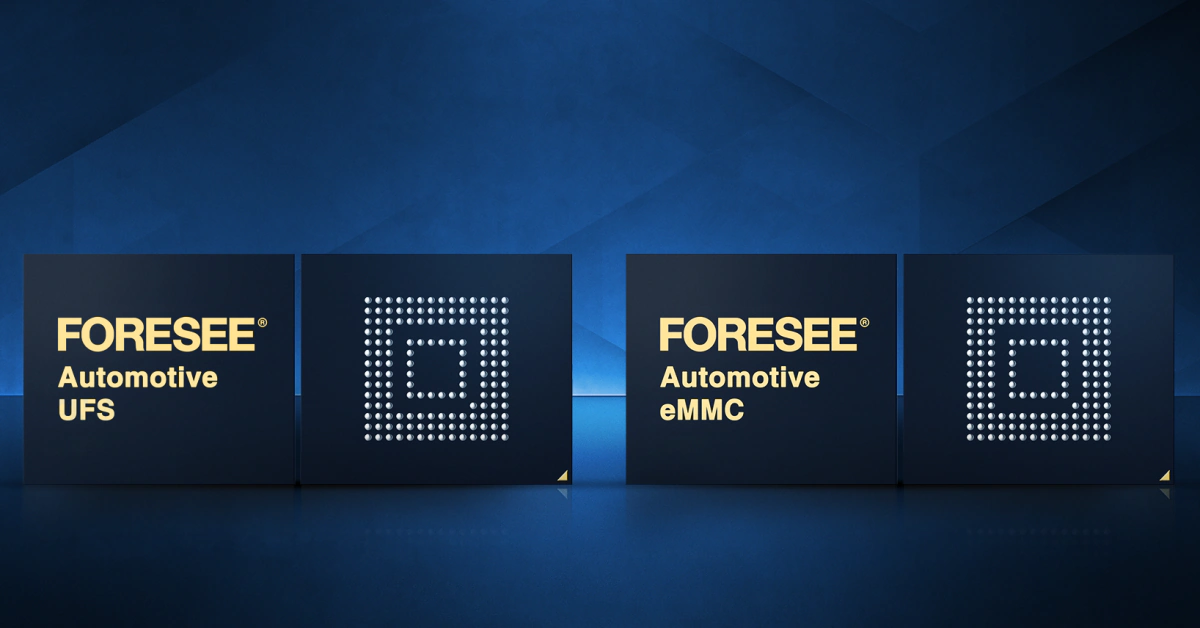
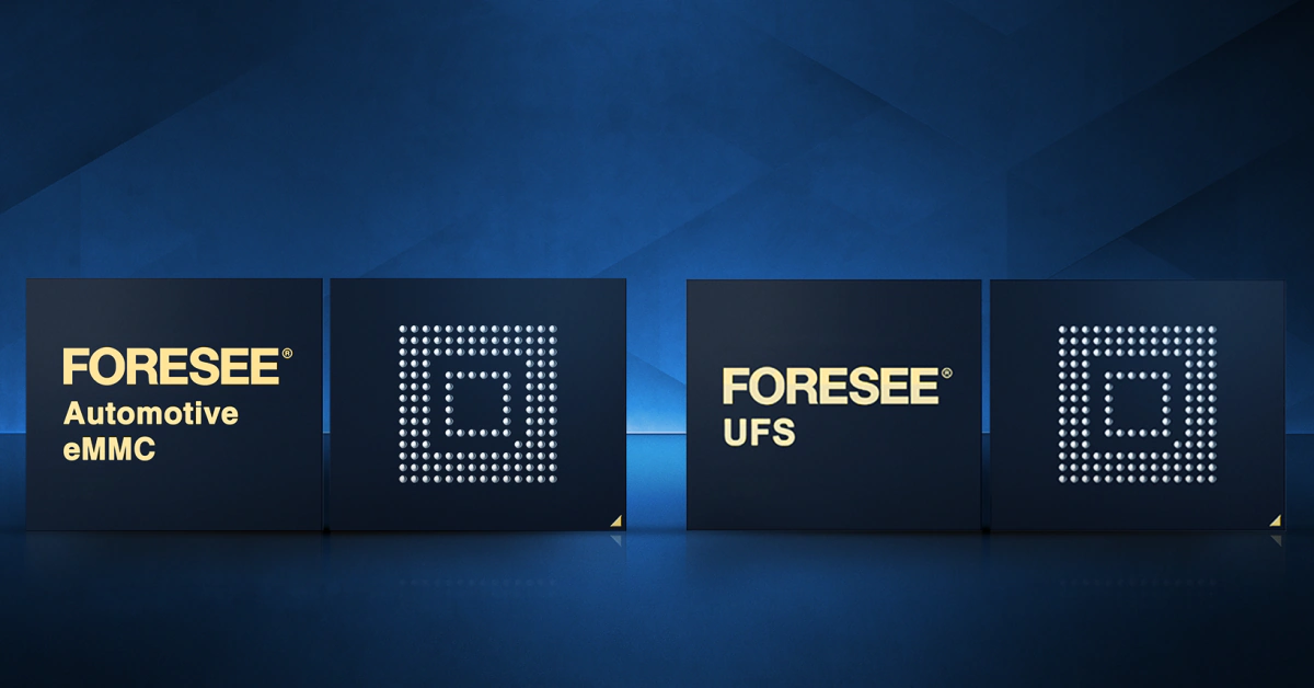
FORESEE automotive storage products from Lexar Enterprise are developed for the write endurance, temperature range, and qualification documentation requirements that OTA-capable automotive placements create. The product line covers both eMMC and UFS in automotive-grade configurations, with differentiation reflecting the access pattern and bandwidth requirements of different OTA application contexts.
For FOTA applications and secondary ECU storage where images are smaller and the primary requirements are write integrity and AEC-Q100 compliance, FORESEE automotive eMMC provides the P/E cycle ratings and qualification documentation that embedded controller programs need. The integrated controller handles wear distribution across the OTA staging partition and the rest of the device storage without requiring application-layer wear management – which matters for programs where the ECU firmware team and the storage selection team don’t have close coordination.
For domain controller and central compute OTA storage where SOTA image sizes are large and update write performance affects the duration of the OTA window, FORESEE automotive UFS delivers the full-duplex interface bandwidth and sequential write performance that large image staging requires. The ability to continue reading from the active partition while writing to the staging partition matters for domain controllers that maintain active software execution during a background OTA download.
FORESEE product documentation includes AEC-Q100 qualification reports, retention characterization data, and failure mode documentation for safety case development and supplier qualification processes. The Lexar Enterprise technical team works through application-specific endurance calculations and partition sizing recommendations before component selection is locked.
Specify OTA Storage at Architecture Stage, Not BOM
The storage specification for an OTA-capable automotive system is a consequential engineering decision. The partition layout affects fail-safe behavior. The component endurance rating determines whether the device survives its fleet lifetime or starts generating field failures in year eight. The AEC-Q100 documentation affects whether the safety case review clears on schedule. None of these get better by deferring them to BOM finalization.
The questions that need answers before the thermal model is locked, before software image sizing is committed, before the software team defines OTA campaign frequency are specific: What’s the expected update image size at EOL, not just at launch? What’s a realistic update frequency if the program hits the competitive pressure that BEV programs routinely face? What does the junction temperature model say for the storage placement under continuous compute load? What documentation does the safety case require from the storage supplier?
Getting those answers early converts automotive OTA storage architecture from a potential program risk into a solved problem. The Lexar Enterprise technical team works with programs at the architecture stage specifically because this is where storage decisions have the most leverage. Contact Lexar Enterprise anytime to discuss partition design, endurance calculations, qualification documentation, or the full OTA storage specification – while decisions are still easy.