

A modern EV architecture has five major storage-consuming nodes. Each has a distinct data profile, endurance budget, and qualification requirement. Over-specifying for one node and under-specifying for another is a common program-level mistake.
| Node | Write Profile | Primary Risk | Min. AEC Grade |
|---|---|---|---|
| BMS Controller | Continuous, high-frequency | Write endurance exhaustion | Grade 1 |
| Powertrain ECU | Episodic writes, high reads | Calibration data corruption | Grade 1 |
| OTA Controller | Episodic large sequential | Lifetime endurance budget | Grade 1 |
| EDR / Event Logger | Burst writes, long retention | Post-collision data loss | Grade 1 + shock/vibe |
| Central Compute / Domain | Mixed, OS-driven | Bandwidth and endurance | Grade 2 (cabin) or Grade 1 |
The BMS is the most write-intensive node. The PCM is the most integrity-sensitive. OTA creates episodic but severe endurance demands that get underestimated during early architecture definition. Those three patterns drive most of the storage selection errors in EV programs.
Battery Management System Storage: The Node That Catches Engineers Off Guard
Cell voltage sampling runs at 1Hz to 100Hz across every cell in the pack. For a 400-cell pack at moderate sampling frequency, you're logging thousands of write operations per minute over a 10- to 15-year vehicle lifecycle. Commercial-grade eMMC isn't rated for that endurance accumulation.
State-of-health data creates a separate retention problem. Cell degradation records, capacity fade curves, and impedance histories need to persist across power cycles, battery replacement events in some architectures, and the full vehicle service life for warranty and regulatory purposes. That's a retention profile requiring industrial or automotive-grade NAND with specified retention characteristics under thermal cycling.
BMS storage specifications come down to four parameters:
- Write endurance: MLC or SLC NAND rather than TLC. Although there are certain TLC parts that can meet BMS requirements, TLC endurance ratings are usually insufficient for continuous high-frequency BMS logging across vehicle lifetime.
- Data retention: 10-year retention at automotive operating temperatures – a substantially different specification than consumer-grade retention ratings measured at moderate ambient temperatures.
- Power-loss data integrity: Sudden power-down during a collision or fault event is a normal BMS operating scenario. Components require integrated power-loss protection or hardware write-protection circuitry to avoid corruption on unplanned shutdown.
- Temperature range: BMS controllers near the battery pack see wide thermal exposure. Industrial-wide temperature ratings (-40°C to +85°C) are the minimum; some placements need automotive-wide ratings reaching +105°C.
The circular-buffer write pattern concentrates write activity on a small portion of the address space if firmware doesn't include wear-leveling logic. Industrial-grade eMMC with integrated controller-level wear leveling handles this transparently. Commodity components often don't. That said, the circular buffer itself is the right design choice for continuous logging. The problem is specifying a storage controller that doesn't account for what that pattern does to write distribution over a 10-year vehicle lifecycle.
Powertrain Control Module: Calibration Integrity Is a Safety Issue
PCM storage looks simpler than BMS on the surface – lower write frequency, smaller data volumes, more predictable access patterns. The complication is data integrity. Calibration maps in PCM flash directly control motor torque output, regenerative braking behavior, and thermal management of the drive system. A corrupted calibration value doesn't produce a graceful diagnostic code. It produces incorrect vehicle behavior. Sometimes unsafe incorrect behavior.
The PCM write profile is episodic rather than continuous. Calibration data gets written during end-of-line programming, dealer reflashing, and OTA calibration updates. Between those events, it's read constantly. That means the endurance specification is less about raw P/E cycle ratings and more about read disturb tolerance – the phenomenon where repeated read operations on one cell cause bit errors in adjacent cells without any write operations taking place.
For PCM placements, specification priorities stack in this order:
- Data integrity and ECC: Hardware error correction sufficient to maintain calibration accuracy across temperature range and service life.
- Read disturb handling: Controller-level management of read disturb for high-read, low-write applications.
- Retention over temperature: Calibration data needs to survive thermal cycling from cold soak to operating temperature repeatedly across vehicle service life.
- Write performance during reflash: OTA and dealer reflash events require fast erase and write cycles to minimize service time.
To be fair, read disturb failure in PCM storage is a low-probability event on most access patterns. The issue is that "most access patterns" for a PCM involves millions of reads across vehicle lifetime. Component selection needs to account for it explicitly.
One interaction that gets underweighted in early program storage specifications: the PCM in most BEV powertrains controls ASIL-B or higher functions. That puts the storage subsystem holding calibration data inside the safety chain.
OTA Update Pipeline Storage: The Endurance Budget Nobody Calculates
OTA update capability is standard in BEV programs. What gets underestimated at the storage specification stage is what fleet-scale OTA activity does to embedded storage endurance across a vehicle's lifetime.
The baseline architecture requires dual-bank partitioning. This allows the incoming update to be written and verified before the switchover, and it enables rollback to the previous image if the update fails validation post-activation. Partition sizing is direct: double the maximum firmware image size, plus overhead for metadata, cryptographic signatures, and update manifests.
The endurance calculation is less direct. Each OTA cycle writes a full firmware image to flash. A vehicle with a 10-year service life receiving monthly updates accumulates 100+ complete image write cycles at minimum. Commercial fleet operators typically push updates more often. Some consumer platforms have been known to push several updates in a single month during active development periods. Multiply that write volume by image size: a domain controller running a full AUTOSAR stack might have a firmware image in the 500MB to 2GB range. That write volume requires industrial-grade eMMC or UFS with SLC caching. TLC NAND-based commercial components can't sustain it.
Power-loss resilience for the update state machine is a separate requirement. If power fails mid-write, the vehicle must boot from the known-good partition without manual intervention. This requires storage with integrated power-loss protection or a carefully designed update state machine that writes only to inactive partitions and commits the switchover atomically.
Event Data Logging: Burst Writes, Long Retention, and Regulatory Requirements
EDR applications create the most demanding write combination in the EV storage architecture: burst write performance during a collision event, physical durability through the impact itself, and long-term data retention in a potentially damaged vehicle. The collision EDR captures a fixed window of pre-crash sensor data at high sample rates – potentially gigabytes of data written in seconds while the vehicle is experiencing shock, deceleration forces, and possible power system failure.
Regulatory requirements for EDR data retention are developing across major markets. The EU General Safety Regulation and NHTSA requirements in the US create minimum data retention standards that affect physical durability standards for EDR storage components – operating temperature range, shock and vibration ratings, and in some cases specific qualification standards that go beyond standard AEC-Q100 thermal and electrical testing.
For continuous fleet telematics logging, the profile resembles the BMS: moderate write frequency, circular buffer operation, long service life accumulation. Telematics data often gets offloaded to cloud storage during connectivity events, which allows local storage buffers to be sized more aggressively since long-term retention moves off-device. BMS health data typically needs to stay local for regulatory and warranty purposes.
AEC-Q100 and ISO 26262 Requirements Across the EV Compute Stack
Most EV compute storage programs treat AEC-Q100 as a checkbox: the component has an automotive-grade variant, the box gets checked, the team moves on. What actually matters is which grade applies to which placement – and whether the specific part number being ordered, not just the product family, carries documentation for the right configuration. That's where programs get surprised at production launch.
AEC-Q100 covers a full stress test sequence across four grades by junction temperature: Grade 0 (up to +150°C) for extreme underhood, Grade 1 (up to +125°C) for most EV compute placements, Grade 2 (up to +105°C) for some cabin nodes, and Grade 3 (up to +85°C) for consumer-adjacent applications where none of this applies. The qualification sequence covers temperature cycling, thermal shock, high-temperature operating life testing, early life failure rate testing, electrostatic discharge characterization, and latch-up testing.
The full specification is maintained by the Automotive Electronics Council , and the AEC-Q100 documents are worth reading directly if you're making grade selection decisions – the stress test sequences and pass/fail criteria are specific enough to matter for supplier evaluation. Placement-specific requirements differ in important ways:
- BMS controller: Grade 1. Wide thermal exposure near the battery pack plus elevated power-loss data protection requirements.
- Powertrain ECU / domain controller: Grade 1. Underhood thermal environment combined with safety-relevant calibration data.
- Central compute / cabin-located nodes: Grade 2 often acceptable with adequate thermal management – verify against your specific thermal model.
- EDR: Grade 1 plus supplemental shock and vibration characterization. The EDR must operate through the collision event, creating mechanical stress requirements beyond standard AEC-Q100 scope.
One verification step that shows up late in some programs: AEC-Q100 qualification on a specific component lot versus qualification of the component family. Suppliers qualify specific product configurations – die revision, package type, memory density. The specific part number being ordered needs to carry AEC-Q100 qualification documentation for that intended configuration, not just that the family has automotive-grade variants. This is a document verification step that belongs in supplier qualification, not production launch.
ISO 26262 creates additional requirements for storage in safety-relevant functions. According to the International Organization for Standardization's ISO 26262 standard , for ASIL-B or higher applications the storage subsystem holding calibration data is part of the safety chain. That means the storage supplier needs to provide:
- FIT rate data suitable for use in FMEDA calculations for the system safety case
- ECC capability documentation covering bit-error-correction depth and defined behavior on detection of uncorrectable errors
- Write protection mechanism characterization for safety-relevant data regions
- Safety manual or equivalent documentation characterizing safety-relevant failure modes and usage constraints
ISO 26262 compliance for a system is a system-level certification. A component can be developed in accordance with ISO 26262 and provide the documentation a system integrator needs to build the safety case, but the ASIL rating lives with the system. That distinction matters when evaluating supplier claims, because "ASIL-B capable component" and "component with documentation sufficient for an ASIL-B system safety case" are two different claims. The second one is the one that affects your program schedule. And the supplier documentation needs to be in hand during architecture definition, not at production launch. Programs that discover their storage supplier can't deliver this documentation after architecture lock are looking at a schedule problem, not a swap-and-continue situation.
ISO 26262 Storage Supplier Checklist
- FIT rate data available for FMEDA calculations
- ECC correction depth documented with failure-mode characterization
- Write protection mechanisms defined and characterized
- Safety manual available for system integrator review
- AEC-Q100 qualification on the specific part number ordered (not just the product family)
- Data retention specifications under thermal cycling documented
FORESEE Automotive Memory for EV Compute Applications
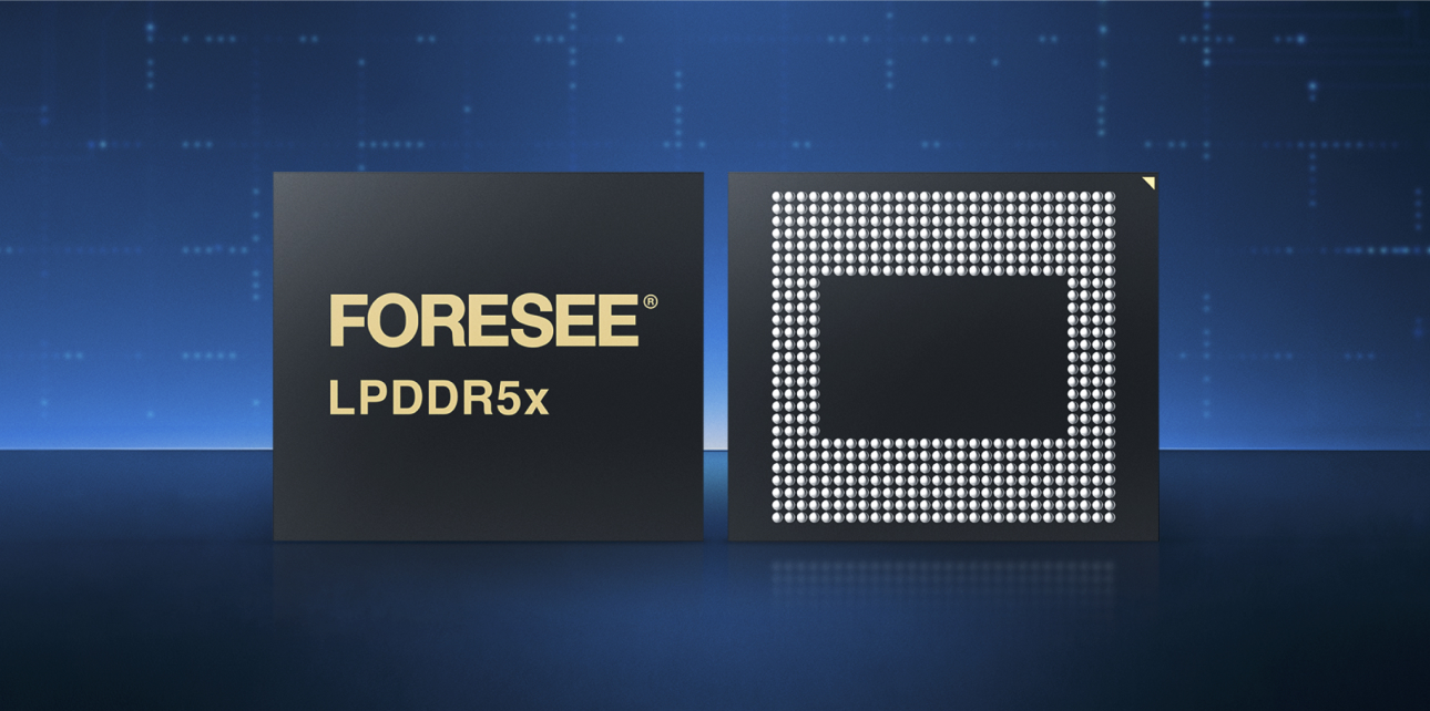
FORESEE is the industrial and automotive memory line from Lexar Enterprise, backed by Longsys manufacturing and over 25 years of embedded memory development. The product lineup addresses EV compute and storage architecture requirements through product lines developed specifically for industrial and automotive operating conditions.
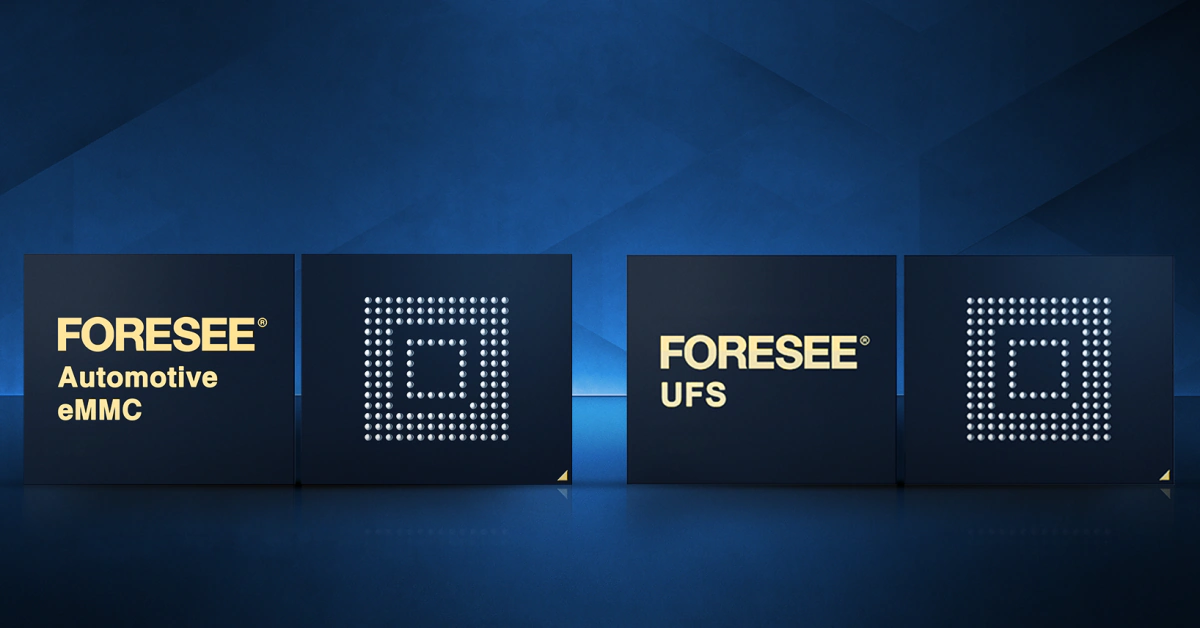
For BMS and powertrain control applications where write endurance and data retention under thermal cycling are primary requirements, FORESEE eMMC components in the automotive series carry AEC-Q100 qualification, industrial-wide temperature ratings, and controller architectures built for the mixed-access patterns that automotive compute workloads generate. Integrated wear leveling and power-loss protection address the BMS circular-buffer write profile and PCM unplanned power-down scenarios without application-layer workarounds.
For OTA update pipeline storage where partition management and write endurance across fleet-scale update cycles are the design drivers, FORESEE UFS components offer the sequential write performance needed for image programming alongside endurance ratings appropriate for long-lifecycle automotive programs. The dual-port architecture in automotive UFS implementations provides the isolation between active and inactive partitions that OTA update reliability requires.
FORESEE product documentation includes FIT rate data and failure mode characterizations needed for ISO 26262 safety-case development. That documentation is available through the Lexar Enterprise technical team – a practical consideration for programs where safety case development timelines are compressed and supplier documentation needs to be in hand early.
Get EV Storage Architecture Right Before Program Lock
The pattern that creates storage problems in automotive programs is specifying the component grade after the architecture decisions are made. By the time the storage part number is selected for BOM purposes, the thermal model is often fixed, the PCB layout is done, and the OTA update partition sizing is committed. Finding that the initially specified component doesn't carry the right AEC-Q100 grade or doesn't have adequate write endurance for the actual update frequency becomes a schedule problem rather than a simple BOM change.
The questions that prevent this scenario are specific: What are the write volumes at each node across vehicle lifetime? What are the retention requirements? What thermal exposure does each placement face? What documentation does the safety case require from the storage supplier? Answering those questions with component specifications rather than estimates changes the nature of the specification work. It's not a large time investment at the architecture stage – and it eliminates a category of program risk that's genuinely difficult to manage once architecture is committed.
The Lexar Enterprise technical team works with programs at the architecture stage specifically because this is where EV compute and storage architecture decisions have the most leverage. Contact the Lexar Enterprise technical team anytime to discuss your storage requirements before the design decisions that constrain component options are finalized.