
IEC 61508 is the base functional safety standard for electrical, electronic, and programmable electronic systems. It doesn’t tell engineers which memory chip to use. What it does is define a framework for calculating whether a system’s safety functions called Safety Instrumented Functions (SIF) can meet a specified probability of dangerous failure per hour.
Safety integrity levels (SIL) are the mechanism for expressing that requirement. SIL 1 through SIL 4 correspond to tolerable probability ranges for dangerous failures, with SIL 4 representing the most stringent. The higher the SIL level, the tighter the constraint on every subsystem that participates in the safety function – including storage.
For storage specifically, three demands emerge from the IEC 61508 SIL framework:
- Quantified failure rates. The component needs a Failure Modes, Effects, and Diagnostic Analysis (FMEDA) that separates safe failures, dangerous detected failures, and dangerous undetected failures. Without this, the system-level PFH calculation can’t be completed.
- Diagnostic coverage. At SIL 2 and above, the architectural constraints in IEC 61508-2 (Route 1H via SFF and HFT, or Route 2H) effectively require quantified diagnostic coverage for dangerous failure modes. Storage components with no on-chip ECC or self-monitoring create a coverage gap.
- Systematic capability (SC). Beyond random hardware failures, IEC 61508 Part 2 addresses systematic failures – faults introduced during design or manufacturing. Storage components used in SIL 2 or higher applications should demonstrate an appropriate Systematic Capability level through their supplier’s development and quality process evidence.
None of this shows up in a standard NAND flash datasheet. It requires either a dedicated safety qualification package from the supplier or a component-level safety analysis performed by the design team.
How IEC 61508 SIL Levels Change Storage Component Specifications
SIL 1 gives designers more latitude. The tolerable PFH range (10-6 to 10-5 dangerous failures per hour) means storage components with basic error detection can often contribute an acceptable hardware fault tolerance contribution, provided the rest of the system architecture compensates where needed. Many lower-complexity safety controllers and industrial monitors fall into this tier.
SIL 2 tightens the requirement considerably. The PFH target moves to 10-7 to 10-6, and the diagnostic coverage requirement becomes a real design constraint. At this level, the storage component’s error correction capability needs to be characterized quantitatively.
An industrial SSD or eMMC device with an internal BCH or LDPC ECC engine and the ability to report correctable vs. uncorrectable error counts can contribute to meeting the diagnostic coverage target. A bare NAND device with no on-die ECC and no system-level error detection layer cannot.
SIL 3 introduces redundancy as a practical necessity. At a PFH target of 10-8 to 10-7, single-component storage solutions generally can’t contribute a fault tolerance that meets the requirement without architectural redundancy. The storage component’s failure mode profile becomes a direct input to the redundancy architecture decision.
SIL 4 applications place demands that go beyond what most commercial NAND or eMMC products can satisfy without extensive qualification work. These applications are rare in the embedded industrial space, but engineers designing them should expect to engage directly with storage suppliers at the engineering level, not just at the procurement level.
| SIL Level | PFH Target Range | Storage ECC Requirement | Redundancy Needed? |
|---|---|---|---|
| SIL 1 | 10-6 ~ 10-5/hr | Basic error detection | Not typically required |
| SIL 2 | 10-7 ~ 10-6/hr | BCH/LDPC with quantified CBER reporting required | Depends on component FMEDA |
| SIL 3 | 10-8 ~ 10-7/hr | Full fault detection + safety supervisor integration | Yes – mirroring or dual-channel |
| SIL 4 | 10-9 ~ 10-8/hr | Full qualification package required – engage supplier directly | Yes – extensive architectural redundancy |
NAND Flash in IEC 61508 Applications – The Three Variables That Matter
Flash memory presents specific challenges in functional safety contexts that don’t arise with other component types. The three variables that most directly affect safety case completeness are ECC architecture, wear leveling determinism, and data retention under mission conditions.
ECC Capability and Diagnostic Coverage
Error correction in NAND flash isn’t a safety feature by default – it’s a reliability mechanism. The distinction matters because IEC 61508 asks for evidence of dangerous failure detection, not just error recovery.
An ECC engine that silently corrects errors without reporting correction events to the host doesn’t contribute to diagnostic coverage; the safety controller has no indication that the storage component is approaching its uncorrectable error threshold.
Storage components that expose corrected bit error rate (CBER) data, report uncorrectable ECC errors as distinct fault codes, and allow the host to monitor spare block consumption over time give the safety architecture something to work with. That health data can feed a watchdog or safety supervisor, contributing to the diagnostic coverage calculation. For a deeper look at how SLC vs MLC vs TLC selection for industrial applications affects error rate behavior, that trade-off is worth reviewing before committing to a cell type for a safety-rated design.
Wear Leveling and Deterministic Behavior
Wear leveling algorithms in managed NAND (eMMC, UFS, industrial SSD) create a layer of non-determinism that functional safety analyses need to account for. The firmware decides when to move data, when to retire bad blocks, and when to perform background operations – and those decisions affect latency, power consumption, and in extreme cases, data availability during an unplanned power cycle.
For safety cases, the question isn’t whether wear leveling is present – it’s whether the firmware behavior is characterized and bounded. A supplier who can document their wear leveling algorithm’s behavior under worst-case conditions, including the latency impact of background operations and the bad block retirement policy, gives the safety engineer defensible evidence.
A supplier who can’t is asking the system designer to treat the storage firmware as a black box – which is difficult to justify to a certification body. The technical detail behind wear leveling firmware behavior matters precisely because of this documentation burden.
Data Retention Under Industrial Mission Profiles
IEC 61508 systems often have long service lives – 15 to 25 years is common in process control. Flash memory data retention degrades with P/E cycle accumulation and with elevated operating temperature.
A typical industrial TLC NAND device (rated for ~3000 P/E cycles at 25°C; ranges vary by vendor) may retain data for the required duration under light write workloads and moderate temperatures. That same device at an elevated industrial operating temperature with higher write activity may not. The embedded memory in harsh environments selection process needs to account for the combined effect of temperature, write load, and retention requirement over the full service life – not just the nominal spec at room temperature.
SLC NAND, despite its lower density, offers significantly better retention characteristics and is worth considering for safety-critical log storage, firmware partitions, and parameter storage where write frequency is low and retention is critical. For applications where those constraints apply, the NAND flash for industrial systems overview covers SLC-specific selection criteria in more detail.
Power-Loss Protection in Safety-Rated Designs
Unexpected power loss is one of the most common causes of storage-related failures in industrial environments. For a functional safety application, the concern goes beyond data corruption – it includes the scenario where a storage device in an undefined intermediate write state causes the safety system to fail to boot correctly, or to boot with incorrect parameter data.
Power-loss protection (PLP) in industrial SSDs and eMMC devices addresses this by using capacitor-backed write buffers that allow the device to complete in-flight write operations and flush volatile cache to non-volatile storage during the power-fail interval.
The protection window matters because it defines the maximum write size that the device can commit safely before power drops below the operational threshold. For safety case documentation, the relevant questions are: what is the guaranteed flush window, what write operations are covered by the PLP design, and what happens to data in the write buffer if the power-fail event exceeds the protection window?
A supplier who can answer these questions with published specifications is providing the evidence the safety engineer needs. One who describes PLP as a general feature without bounding parameters isn’t. The design considerations behind power-loss protection design in industrial SSDs covers the architectural options worth evaluating.
Building the Storage Qualification Record for an IEC 61508 Safety Case
A safety case – the structured argument that a system meets its safety requirements – requires evidence for every safety claim. For storage components, that evidence typically needs to address three areas that certification assessors will examine.
- FMEDA documentation. A completed Failure Modes, Effects, and Diagnostic Analysis for the storage component, identifying safe failure fractions, dangerous detected failure rates, and dangerous undetected failure rates. This document is the direct input to the system-level PFH calculation. Without it, the calculation rests on assumptions the assessor won’t accept.
- Qualification test evidence. Operating temperature range testing, endurance testing across the rated P/E cycles, and data retention verification. For wide-temperature industrial applications, this means test data at the thermal extremes of the rated range – not just at room temperature. The memory validation and testing reference covers the test categories that industrial qualification programs typically include.
- Systematic capability evidence. Documentation of the supplier’s development process, quality management system, and change management practices – the evidence base for the SC level claimed for the component. For SIL 2 applications, IEC 61508-2 Table D.2 provides the recommended techniques and measures that the development process should address. Suppliers producing standard commercial components without a safety qualification program cannot provide this evidence as a matter of course.
The storage specification checklist framework is a useful starting point for capturing which of these data points are available from a supplier before a design review. For further reference on what certification assessors look for, the IEC functional safety resource center publishes guidance documents for IEC 61508 implementers.
Industrial Storage From FORESEE Engineering – What’s Relevant to Safety Applications
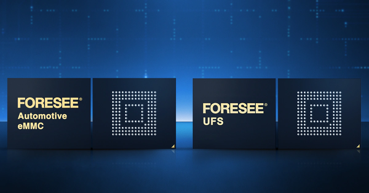
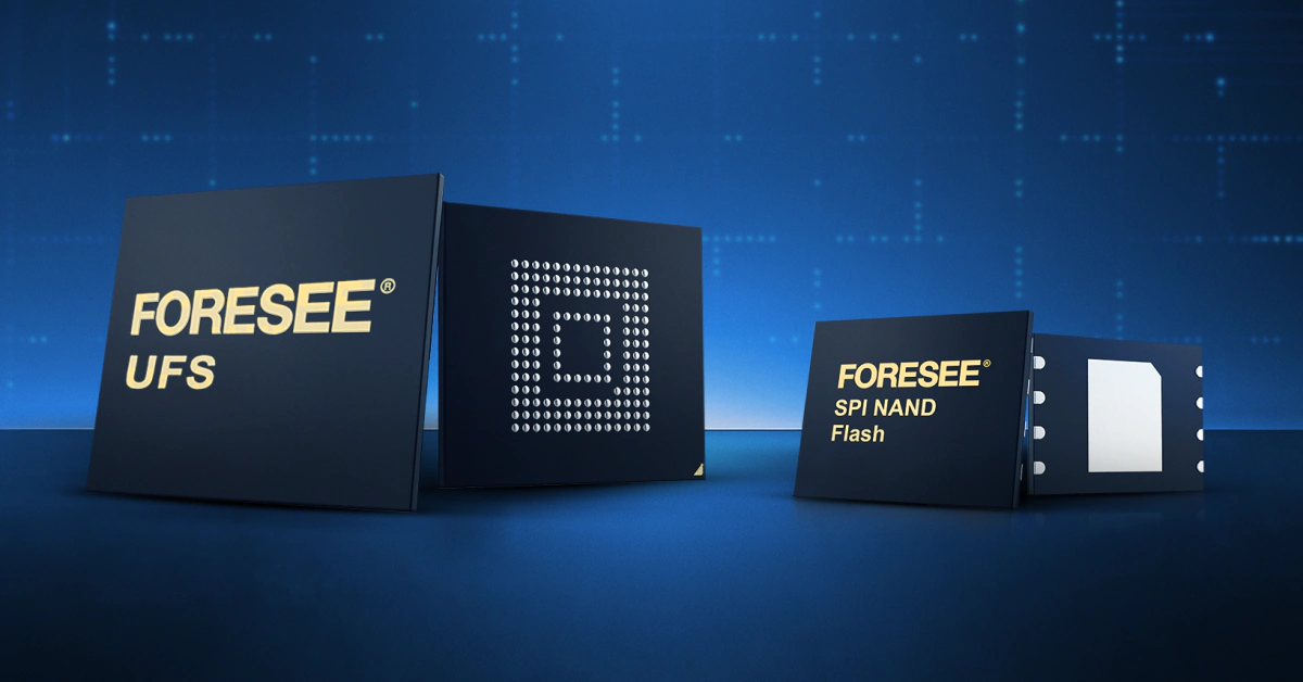
Lexar Enterprise’s industrial embedded storage portfolio, developed on FORESEE engineering, includes several product characteristics that align directly with IEC 61508 functional safety requirements. This section is an honest account of what’s documented – not a claim of IEC 61508 certification, which requires a formal third-party assessment process that varies by application and integrator.
The industrial-grade SSDs in the portfolio carry operating temperature ratings of -40°C to +85°C or -40°C to +105°C, with endurance specifications documented at the thermal extremes of the rated range. That thermal qualification data is the kind of evidence a safety case needs for temperature-sensitive applications.
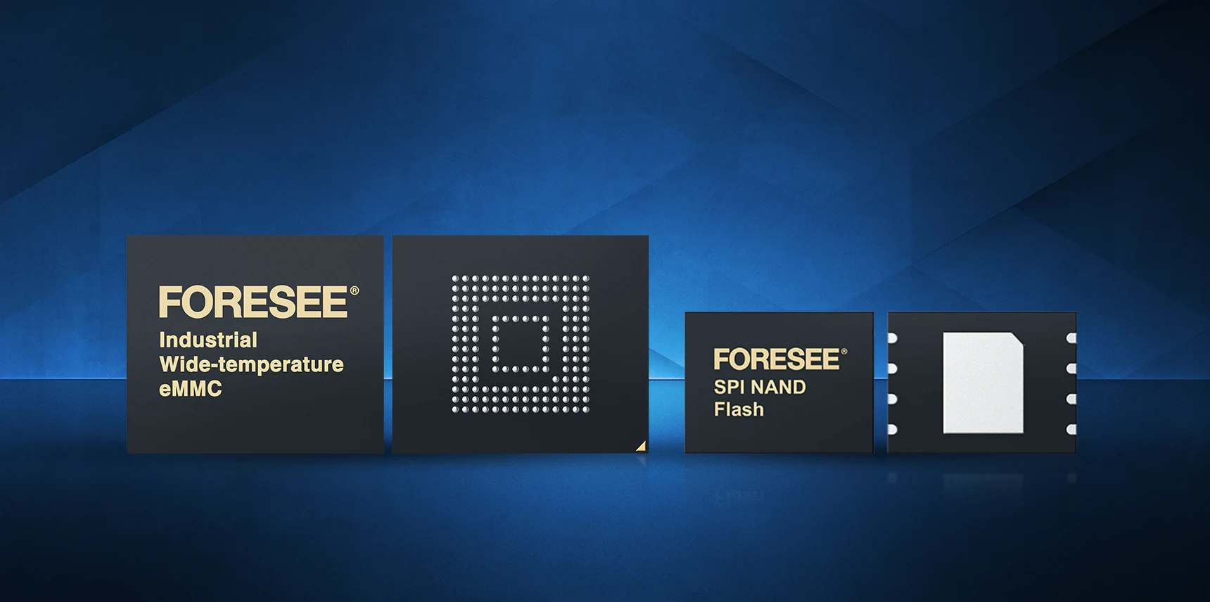
The industrial wide-temperature eMMC variants support operating ranges of -40°C to +85°C with documented P/E cycle endurance ratings. The NAND architecture – including SLC variants in the portfolio – contributes meaningfully to the data retention argument for long-lifecycle safety applications. SLC NAND’s inherently lower bit error rate under aged conditions is a relevant factor when service life extends beyond 15 years.
The industrial SSD products include capacitor-backed PLP design with write cache flush capability. The specific protection window and covered write operations are in the product datasheets, which is the correct place to verify these parameters before committing them to a safety case.
Lexar Enterprise’s engineering team can provide application-specific guidance on PLP behavior for SIL-relevant write scenarios. For procurement managers evaluating long-term supply continuity, Lexar Enterprise offers long product lifecycle commitments, documented change notification processes, and supply chain continuity support. Find a Lexar Enterprise distributor to discuss stocking arrangements and lifecycle support for safety-critical programs.
Frequently Asked Questions
Does IEC 61508 specify which storage technology to use?
No. The standard defines failure rate and diagnostic coverage requirements that a storage component must satisfy to contribute to a SIL-rated system. The specific technology – NAND flash, eMMC, NOR flash, industrial SSD – is a design decision. What IEC 61508 constrains is the evidence required to justify that decision in a safety case.
Can a standard commercial eMMC or SSD be used in an IEC 61508 application?
Potentially, at SIL 1, with adequate system-level diagnostic coverage compensating for gaps in component-level fault detection. At SIL 2 and above, the absence of a component FMEDA makes the system-level PFH calculation difficult to complete with credible numbers. Most certification assessors will require either a safety-qualified component or a detailed component safety analysis performed by the integrator – which is a significant engineering effort.
What is the difference between IEC 61508 and ISO 26262 for storage selection?
ISO 26262 is the automotive functional safety standard derived from IEC 61508. Both use SIL-equivalent metrics (ASIL A through D in ISO 26262), both require hardware failure rate quantification, and both impose diagnostic coverage requirements. The primary differences are in the automotive-specific requirements: AEC-Q100 qualification, extended thermal ranges, and the ASIL decomposition methodology. A storage component that meets the evidence requirements for IEC 61508 SIL 2 may not automatically satisfy ISO 26262 ASIL B without automotive-grade process qualification – the two standards share a framework but diverge on qualification process requirements.
How does PLC storage reliability relate to SIL requirements?
In a safety PLC, the storage subsystem typically holds firmware, safety parameters (safety configuration data, and event logs). Storage failures here can directly affect the safety function’s availability, so the storage subsystem’s failure rate and diagnostic coverage must be included in the PLC’s overall PFH calculation and safety case.
The safety requirements on that storage depend on what functions those data elements support. Firmware storage failure that prevents correct PLC startup is a safety-relevant failure mode. Parameter storage corruption that causes incorrect setpoint loading is a safety-relevant failure mode.
Event log storage failure alone may not be – depending on whether the event log is part of the safety function or purely an operational record. The IEC 61508 safety analysis for the PLC maps each storage function to a safety requirement level, and that mapping drives the component selection criteria for each partition.
What documentation should a storage supplier provide for a safety case?
At minimum – a component FMEDA with quantified safe and dangerous failure rates, operating temperature qualification data covering the full rated range, endurance and retention characterization at temperature, and a description of the supplier’s change management and notification process. For SIL 2 and above, Systematic Capability evidence aligned with the IEC 61508-2 development process requirements is also expected. Suppliers who can provide these documents as part of a standard safety data package reduce the engineering burden on the integrator considerably.
Selecting Storage for an IEC 61508 or SIL-Rated System?
Lexar Enterprise’s engineering team works with industrial OEMs on storage qualification, FMEDA support, and long-lifecycle supply planning. Request documentation or discuss your application requirements directly with our team.