
A telematics control unit is the vehicle’s cellular gateway – the hardware module that manages 4G/5G connectivity, V2X communications, GPS/GNSS positioning, over-the-air update delivery, and event data recording. In a modern connected vehicle, the TCU runs continuously, even when the ignition is off, monitoring vehicle state and logging data to satisfy both regulatory and OEM requirements.
Unlike an infotainment head unit or an ADAS domain controller, the TCU doesn’t process high-bandwidth sensor streams. It manages a very different workload: frequent small writes (event records, connectivity logs, GPS coordinates), occasional large writes (OTA firmware staging), continuous low-power operation, and cold-start requirements that come with strict timing windows.
TCU Storage Requirements by Subsystem Function
The first step in sizing and selecting TCU storage is mapping the actual workload by subsystem.
Always-On Event Data Logging
Event data logging is the most demanding storage workload in most TCU designs. The event data recorder (EDR) function writes small records at irregular intervals throughout the vehicle’s operational and standby periods. The write pattern is continuous, not bursty. The storage cannot be powered down to save energy as a removable flash card might, because losing a logging window carries regulatory consequences for certain vehicle categories.
This write profile drives write endurance to the top of the specification priority list. The eMMC component selected for a TCU application needs to be evaluated on its write amplification factor under small, random-write workloads. Understanding wear-leveling firmware behavior is critical: an aggressive algorithm under a continuous small-write workload can produce write amplification factors of 3x to 10x over nominal, directly eroding the P/E cycle budget and shortening usable component life.
GPS and Mapping Data Storage
GPS coordinate logging is a sequential append workload: low write bandwidth, continuous, with minimal read activity during normal operation. Mapping data follows a different pattern: large sequential reads when routing or map tile rendering is active, followed by long idle periods.
A TCU that caches HD map tiles or routing graphs locally needs enough capacity in this partition to hold a meaningful geographic region without constant cellular updates.
The dominant specification for this function is data retention rather than write endurance. Map data written during factory provisioning or a major OTA update needs to survive the full vehicle lifecycle without a refresh write cycle.
OTA Update Staging
OTA update staging places the most demanding single-write events on the TCU’s storage. A firmware package for a connected vehicle ECU can range from 100MB to 2GB. The TCU needs enough capacity to hold both the active firmware image and the incoming update simultaneously. The active partition cannot be touched during staging because a failed update that corrupts the active image bricks the ECU it was meant to update.
This drives minimum-capacity decisions more than most teams initially plan for and places a premium on sequential write throughput during the staging window.
V2X Connectivity Buffering
C-V2X safety message handling requires a low-latency write, distinct from event logging. Safety-critical V2X records need to be committed to storage before the write acknowledgment is returned to the application layer. This demands a storage component with a predictable write latency profile under sustained queue depth. Selecting NAND flash for automotive applications requires close attention to worst-case write latency, not just average-case bandwidth.
eMMC vs UFS for Telematics Control Unit Platforms
The comparison between eMMC and UFS in a TCU application is more nuanced than a raw performance table suggests. UFS 2.x and 3.x offer superior peak throughput and lower latency for mobile-optimized workloads. But the TCU’s operating conditions impose constraints that shift the advantage in ways not obvious from spec sheets alone. Here’s how they compare across the metrics that actually matter for telematics storage design:
| Evaluation Factor | eMMC 5.1 | UFS 2.x / 3.x | TCU Verdict |
|---|---|---|---|
| Sequential write — logging workload | Predictable, deterministic latency | Higher throughput; better at deep queue | eMMC ✓ |
| Power state in ignition-off standby | Fast, simple sleep/idle transitions | H8 deep sleep — exit latency can penalize logging resume | eMMC ✓ |
| Boot time (cold start) | 150–300ms typical | <100ms at HS-G4 (requires full UFS 3.x phy support) | UFS (if host supports it) |
| AEC-Q100 automotive qualification | Grade 1 & 2 available | Grade 1 & 2 available | Tie |
| Host controller complexity | Single data lane, simpler protocol stack | Higher phy/firmware implementation overhead | eMMC ✓ |
| Mixed read/write peak workloads | Adequate for TCU logging profile | Superior command queue depth | UFS (OTA-heavy platforms) |
For the event logging workload, eMMC 5.1 with cache flush mode provides predictable commit latency. The interface is simpler: a single data lane, command queuing up to 32 entries, and a well-understood power state machine that automotive firmware teams are more experienced in managing. The UFS and eMMC differences extend beyond throughput to include host controller requirements, protocol stack overhead, and the initialization sequence, which directly affects cold-start boot time.
Power state compatibility is where the TCU application diverges most sharply from mobile-device assumptions. A smartphone puts its UFS storage into deep sleep (H8 state) when the application processor suspends. The TCU cannot do this.
Even in ignition-off standby, event logging and telematics functions may continue at reduced frequency, requiring storage to remain accessible without a full power-on reset sequence. eMMC’s sleep state transition is faster and more deterministic than UFS H8 exit for most automotive controller implementations.
AEC-Q100 Qualification and TCU Storage Requirements for Underhood Placement
The AEC-Q100 qualification standard defines the reliability testing requirements for integrated circuits used in automotive applications. For embedded storage in a TCU, the grade classification determines the operating temperature range the component is rated to sustain.
| AEC-Q100 Grade | Operating Range | Typical TCU Placement | TCU Suitability |
|---|---|---|---|
| Grade 0 | -40°C to +150°C | Extreme underhood, near the engine block | Rare for TCUs |
| Grade 1 | -40°C to +125°C | Engine compartment, underhood-mounted | Required (underhood only) |
| Grade 2 — Most TCUs ✓ | -40°C to +105°C | Trunk, A-pillar, under-seat, behind-dash | Minimum required |
| Grade 3 | -40°C to +85°C | Climate-controlled passenger compartment | Not sufficient |
Most TCU designs are not mounted in the engine bay. The cellular and GPS antenna coupling requirements typically place the TCU in the trunk, under a seat, or in the A-pillar region – environments where sustained ambient temperatures reliably stay within the Grade 2 envelope. Grade 2 qualification is the minimum acceptable specification for a TCU eMMC, not a conservative choice. Specifying a Grade 3 commercial-temperature part introduces real risk at peak summer parking temperatures in warm climates.
AEC-Q100 Grade 2 qualification requires the component to pass a specific battery of stress tests beyond the simple temperature rating. Critical tests include high-temperature operating life (HTOL) at +125°C for 1,000 hours under bias, temperature cycling between -40°C and +125°C for 1,000 cycles, and high-temperature storage life (HTSL) at +150°C for 1000 hours without bias – the last being the primary data retention validation. These tests validate NAND cell charge retention, controller firmware integrity, and solder joint reliability across the actual vehicle use case.
Data Retention and Write Endurance Over a 10+ Year TCU Storage Lifecycle
The math on TCU write endurance is less forgiving than it looks at first pass. Here is a realistic workload model for an active telematics deployment:
- Event logging: 500MB – 1GB written per day across all logging functions
- OTA updates: 4 to8 updates per year, averaging 500MB per update package
- Map data refreshes: 2 to 4 per year at 200MB – 800MB per refresh
TCU Write Endurance — 10-Year Lifecycle Math
| Host writes (logging only, 10 yrs) | 1.8TB – 3.6TB |
| Write amplification factor (small-block pattern) | 3× – 5× |
| Physical NAND writes (before OTA + map traffic) | 5.4TB – 18TB |
| Required NAND cell type | SLC or pSLC — TLC will not close this budget |
The choice among SLC, MLC, and TLC NAND types comes down to P/E cycle budgets: SLC NAND supports 100,000 or more P/E cycles per cell, MLC delivers 3,000 to 10,000 cycles, and TLC drops further to 1,000 to 3,000 cycles. For a continuous write workload over a decade-plus lifecycle, SLC or pSLC (pseudo-SLC configured from MLC cells) is the architecture that closes the endurance budget. TLC selected purely on cost will not meet the lifecycle in most realistic TCU logging deployments.
Data retention is the second half of the equation. JEDEC standards require automotive-grade eMMC to demonstrate 10-year data retention at the rated operating temperature. For a part operating at 85°C average junction temperature, the retention bake test at 150°C for 1000 hours is the accelerated validation that maps to this real-world condition. According to the JEDEC stress test standard JESD47, automotive-grade qualification evidence must include these results before a component is approved for vehicle production. A component that meets the AEC-Q100 Grade 2 package has passed. A component without documented qualification evidence has not.
FORESEE Automotive eMMC Integration for TCU Platforms
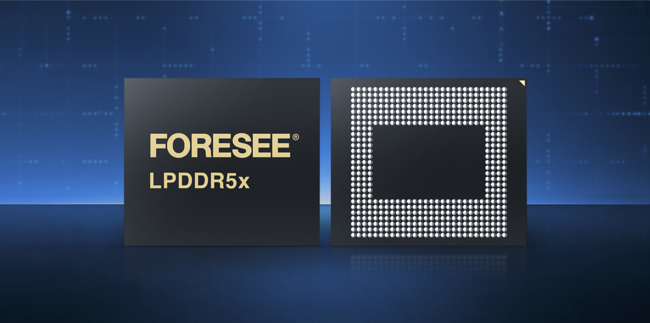
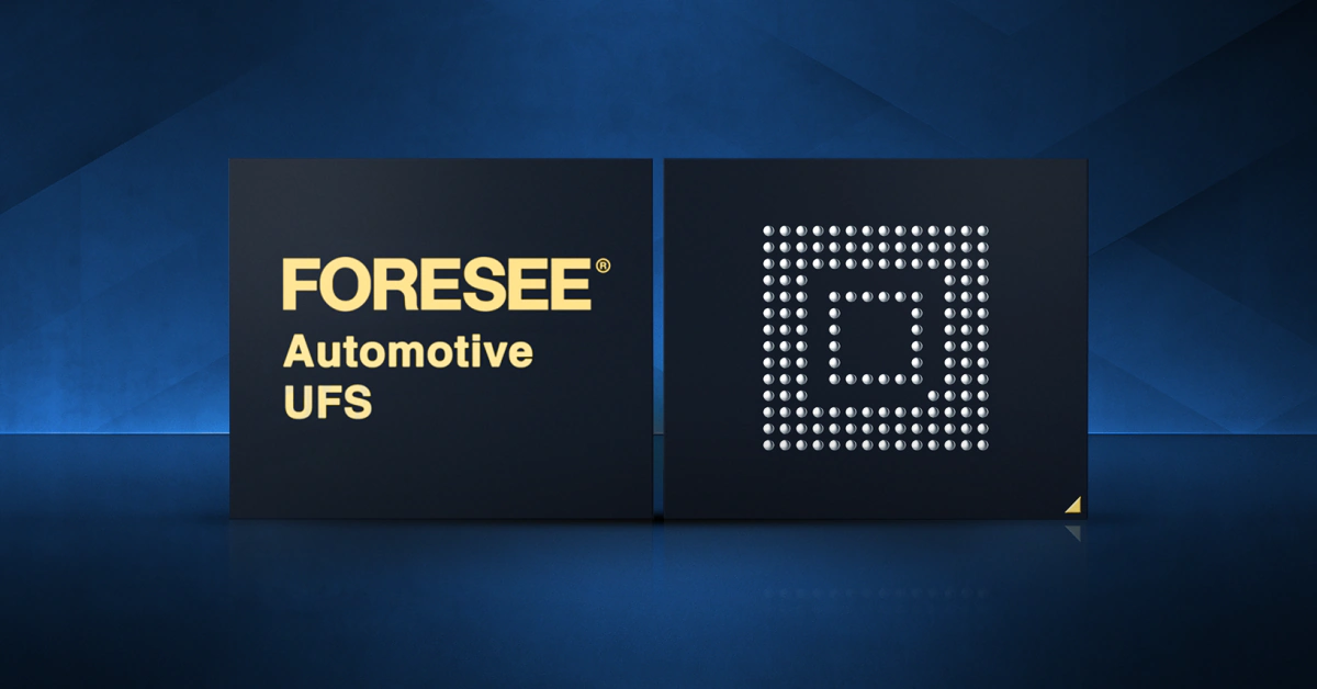
FORESEE is Lexar Enterprise’s automotive-qualified embedded memory product line, developed specifically for vehicle applications where AEC-Q100 Grade 2 certification, extended temperature operation, and long-term supply continuity are non-negotiable requirements.
For TCU applications, the FORESEE automotive eMMC lineup addresses the full set of connected vehicle storage requirements covered in this guide:
- Temperature rating: AEC-Q100 Grade 2, -40°C to +105°C operating ambient
- Interface: JEDEC eMMC 5.1, compatible with automotive-class host controllers
- NAND architecture: Configured for automotive-grade endurance to support always-on logging workloads over 10+ year lifecycles
- Power states: Sleep and idle state transitions validated for TCU power sequencing – no UFS H8 exit latency penalty on logging resume
- Capacity range: 8GB to 256GB, covering TCU configurations from event-data-only to full OTA staging with HD map caching
- Supply continuity: Automotive-grade component lifecycle commitment, with product change notifications required before any die or firmware revision
PPAP Documentation and Qualification Support for Automotive eMMC
Connected vehicle programs that source eMMC from a memory supplier need a complete Production Part Approval Process (PPAP) package to satisfy Tier 1 and OEM supplier quality requirements.
A Level 3 PPAP submission for automotive eMMC typically includes:
- Design FMEA (dFMEA) covering memory failure modes and their effects on TCU system behavior
- Process FMEA (pFMEA) covering manufacturing process failure modes
- Control Plan documenting inspection checkpoints and acceptance criteria
- First Article Inspection (FAI) report with measurement results from production samples
- AEC-Q100 qualification test reports, including HTOL, temperature cycling, and HTSL data
- Material and substance of concern declarations (REACH, RoHS, conflict minerals)
- Dimensional and functional measurement system analysis
Lexar Enterprise supports PPAP Level 3 submissions for FORESEE automotive eMMC customers, including access to qualification test data packages, material declarations, and engineering support for application-specific evaluation.
Frequently Asked Questions
Does AEC-Q100 Grade 2 qualification meet TCU requirements for all vehicle placements?
Grade 2 covers the -40°C to +105°C ambient operating range, appropriate for trunk, cabin, and behind-instrument-panel TCU placements. Most connected vehicle TCU placements are outside the engine bay and are served by Grade 2, but complete a thermal survey of the specific mounting location before finalizing the component grade requirement.
Why does eMMC often outperform UFS for TCU logging workloads despite lower peak throughput?
The TCU logging workload is dominated by continuous low-bandwidth, small writes, rather than peak sequential throughput. eMMC’s simpler power-state machine better matches the always-on, low-latency logging access pattern of a TCU in ignition-off standby.
How much storage capacity does a TCU need for OTA update staging?
The minimum OTA staging partition must accommodate the largest anticipated firmware update package without displacing the active firmware image. For a TCU managing multiple ECU OTA deliveries, this can require 2GB-4GB of dedicated staging capacity.
What PPAP level does a Tier 1 automotive supplier typically require for eMMC components?
Most Tier 1 automotive suppliers require Level 3 PPAP for active components, including embedded memory. Level 3 requires submission of all documents and sample parts to the customer. The customer’s supplier quality manual defines the specific contents, but they typically include the design FMEA, process FMEA, control plan, measurement system analysis, initial process study, qualified laboratory documentation, and AEC-Q100 qualification test reports.
Can FORESEE automotive eMMC support both TCU and ADAS applications from the same component family?
FORESEE automotive eMMC is designed to cover a broad range of automotive embedded storage, including TCU, gateway controllers, and some ADAS applications. However, TCU and high-bandwidth ADAS domain controller workloads differ significantly. Lexar Enterprise application engineers support workload-specific selection and qualification planning for both application categories.
FORESEE automotive eMMC from Lexar Enterprise is qualified, documented, and supported through the full PPAP process to meet these requirements in connected vehicle programs. Contact the Lexar Enterprise automotive team to discuss your TCU platform specifications, request qualification documentation, or begin the application engineering process for your program’s memory selection.